
Concept v0.2
Historical: the v0.2 concept of 2026-10-25, kept as it was. The current design is in the README,
description/robot.yamland decisions.md; the figures, the drawing (25 DOF with grippers) and the open questions below are not updated.
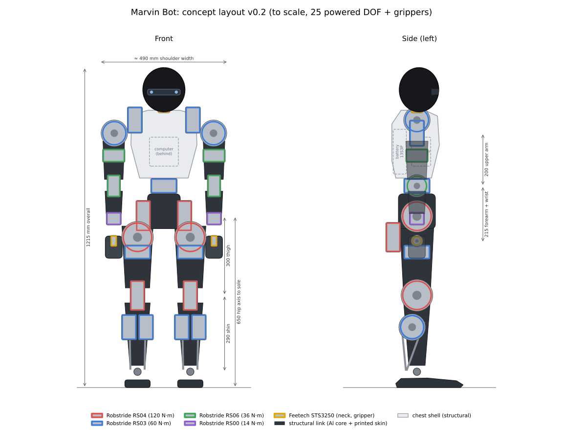
The drawing is to scale and shows every powered joint, coloured by actuator model. It is drawn by tools/sketch_concept.py, which takes the leg and overall heights and the ankle motor from description/robot.yaml. The changes from v0.1 and their reasons are in decisions.md.
Proportions
Section titled “Proportions”| Height | 1.438 m (longer torso and legs, 2026-10-29; 1.288 m before; 1.215 m in the concept) |
| Hip axis to sole | 0.70 m (49% of height; 0.65 m in the concept, sized for 17–18 cm stairs) |
| Thigh, shin | 0.325 m, 0.315 m (0.30 m, 0.29 m in the concept) |
| Ankle axis height | 0.06 m |
| Shoulder width | 0.416 m (~0.49 m in the concept) |
| Upper arm, forearm to wrist pitch, hand | 0.20 m, 0.188 m, 0.181 m |
| Head | ~0.16 m wide, ~0.17 m tall |
Design language
Section titled “Design language”The goal is a robot that looks finished without a separate cover, because the visible parts are the structure.
- Limbs: graphite structural links that taper from joint to joint, with brushed-aluminium actuator caps showing at every joint. The caps are the actuators’ own housings or thin machined covers that also act as heat spreaders.
- Torso: a light-coloured structural chest piece over an aluminium spine, holding the computer, with the battery behind and below it in a quick-release cradle.
- Head: a smooth, glossy dark egg shape with no face. The depth camera sits behind an open slot, not behind glass, because a cover window reflects the camera’s IR pattern.
- Colour: two-tone, light structural pieces against dark links. The exact scheme is open.
- Optional covers: soft covers or padding can be added later at impact points without changing the structure.
Structure
Section titled “Structure”- Load path: machined 6061 cores through each leg and the pelvis. Printed shells (white PETG) clip on over the frame and carry no load.
- Part size: parts are sized for a desktop CNC mill with about 200 × 150 mm usable area. Long thigh and shin cores are split into pinned segments or ordered from an online machining service.
- Bearings: far-side bearings at hip roll, hip yaw and knee; a crossed-roller bearing at the waist.
- Ankles: two RS03 motors side by side in the calf, 125 mm below the knee, turn 65 mm cranks on their outer faces; ~166 mm push rods with spherical rod ends drive the foot 55 mm behind and ±55 mm beside the ankle axis (
tools/ankle_linkage.py). - Feet: flat aluminium plates with replaceable rubber or TPU soles; no toe joint in v1.
- Cables: each limb’s CAN and power run through the joints with service loops; connectors at each limb root so a limb can be removed as a unit.
Stair climbing (status, open issues and options) has its own note: stairs.md.
Open design questions for phase 1
Section titled “Open design questions for phase 1”- Knee motor at the joint (v1) or near the hip with a linkage: decided by simulated leg inertia and torque.
- Leg length: compare 0.62, 0.65 and 0.69 m hip-to-sole on stairs.
- Exact ankle linkage geometry, push-rod loads and rod-end size.
- Colour scheme and finish of the printed shells.
This page is generated from docs/design/concept.md in the repository.